Drawworks Page
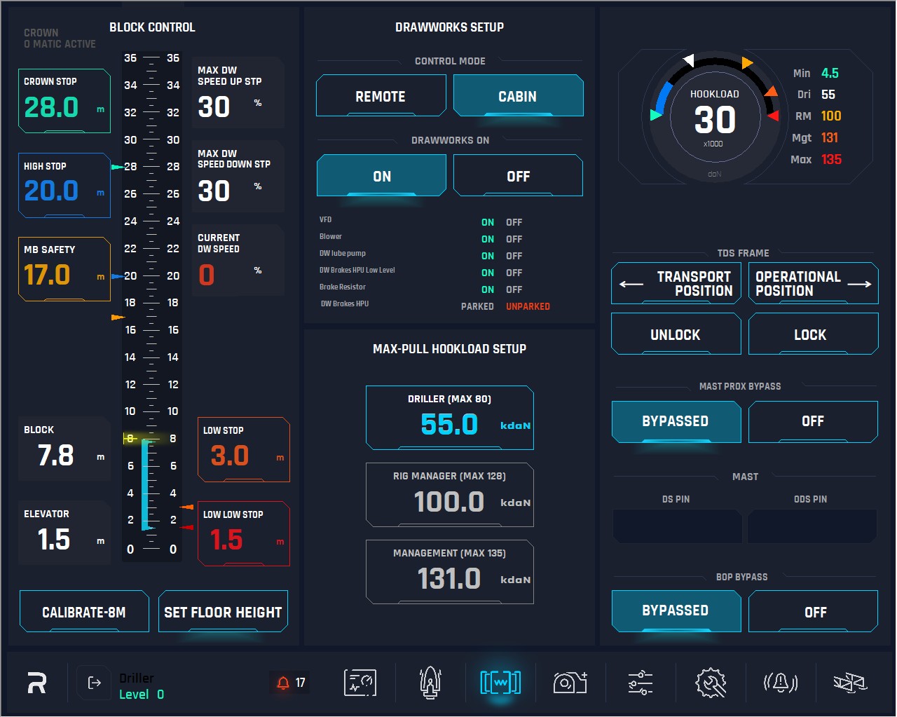
1. Center Scale: Represents the full height and scale of the mast. It also includes a function where, when the block height reaches the MB (Monkey Board) point and passes it, the section from 17m to 36m (Ground Level) is highlighted in yellow.
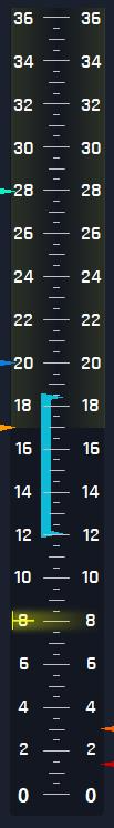
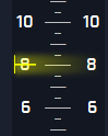
There is a mark on the mast (also represented on the scale by a yellow triangle at 8m) at a fixed height, where the operator should stop the elevator and perform the calibration.
Ground Level: Left Scale Represents the Ground Level to the top of the mast.
Rig Floor Level: Right Scale Represents Rig Floor Level to the top of the mast.
2. Block indicator: This indicates the distance from the rig floor to the top of the block.
Block = ELEVATOR position + 6.40m
3. Elevator: This indicates the distance from the rig floor to the bottom of the elevator.
4. Max (set) DW Speed: This indicates the max speed the Drawworks currently set at in %, only visualization. This is set in the Ops Parameter Page.
5. Current DW Speed: This is an indicator to show the actual operating DW velocity, in percentage (%).
6. Crown Stop: This is visualization display for the driller, and the button to show and the set point for Crown STOP (Ground Level).
Behavior: (28m-32m) always ramp down to 5% and apply caliper brakes as soon as block get into Crown stop zone, (if block is travelling at high speed and system detect that the motor will not stop the block, engage the caliper brakes) Bypass cannot be used by driller, it is requiring rig management logging to change crown saver height.
When the rig manager logs on this button will become active. After click on the button, a window with numeric keyboard must pop up to allow user to insert the numeric values.
7. High Stop: This is to display and to set point for High STOP (Ground Level).
Behavior: (20-28) always ramp down to 5%, stop drawworks by motor if driller does not do anything. If the block is travelling at high speed and the system detects that the motor will not stop the block, engage the caliper brakes. If the bypass button on the right joystick is pressed by driller before entering and/or while in the high stop zone, the block will continue to rise at 5% speed. Downwards movement is not restricted to 5% speed.
A window with numeric keyboard must pop up on click on this button to allow the user to insert the numeric values. These values will be limited by his hierarchy.
8. Monkey Board Stop: This display and button to show and set the point Monkey Board STOP (Ground Level). To be able to adjust this value will be limited by hierarchy, this is not driller settable.
Behavior: (17m fixed – E-tech accessible only) It is not bypass able, it ramps down to 5% and then stops by motor. Monkey board interlock only applies if either the swivel or link tilt are not in float mode. Above the Monkey Board, tilt functions for swivel and link are not allowed to operate (Float mode must maintain above MB).
A window with numeric keyboard must pop up on click on this button to allow user to insert the numeric values. Numeric values are limited to the hierarchy allows.
9. Low Stop: This is a visualization display and button to show the set point for Low STOP (Rig Floor Level).
Behavior: (1.5m above low low stop – E-Tech accessible only) always ramp down to 5%, stop drawworks by motor if driller does not do anything. If the block is travelling at high speed and the system detects that the motor will not stop the block, engage the caliper brakes. If bypass is pressed by driller before entering the low stop zone the block will continue to lower at 5% speed. If the driller presses bypass when in the low stop zone, it will allow him to lower the block at that 5% speed. Upwards movement is not restricted to 5% speed.
A window with numeric keyboard must pop up on click on this button to allow user to insert the numeric values. Only can be activated by hierarchy preferences.
Low Low Stop: This is a visualization display and button to show and the set point for Low STOP (Rig Floor Level).
Behavior: (1.5m above floor set height – E-Tech accessible only) always ramp down to 5% and apply caliper brakes as soon as block get into low low stop zone.
KEMS, if the block is travelling at high speed and the system detects that the motor will not stop the block, engage the caliper brakes. If bypass is pressed by driller before entering the low stop zone the block will continue to lower at 5% speed. If the driller presses bypass when in the low low stop zone, this allows him to bump down the joystick, brakes release, and he continues downwards at 5% speed.
A window with numeric keyboard must pop up on click on this button to allow user to insert the numeric values. The values will be the distance above “set floor height”.
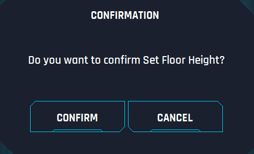
11. Set Floor Height: This button is to set the 0m for the system. As the rig floor is a moving part of the substructure and it is not always at the same height. Rig Crew needs to set the 0m for the block position system. The driller will move the elevators downwards till they reach the rig floor and then press the button, and the current BHE must be set to 0m. When pushing this button, a window must pop up asking to confirm the action user wants to take, CONFIRM or NO.

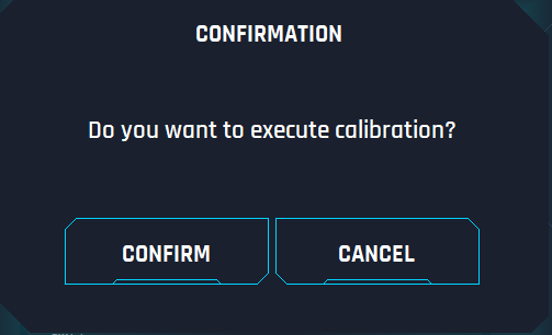
12. Calibration Button: The function of this button is to teach the system the current elevator position (block Height). There is a mark in the mast (it is also represented on the scale by a yellow triangle at 8m) at a certain height which is fixed, and the operator will stop the elevators at that mark then user will press CALIBRATE button. After clicking on the button, a pop-up window showing “Calibration has been done” will appear. For calibration the bottom of elevators will be the reference point.

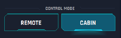
13. Control Mode: This option is to switch the mode of control for Drawworks, by selecting cabin user can use the RIGHT JOYSTICK to control the Drawworks. By selecting remote, user can control the Drawworks from the remote controller which is saved at the VFD.
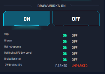
14. Drawworks on: This option is to turn on or off the VFD for the drawworks. Below these buttons are the validation of permissive for the VFD, all must be green before joystick is activated.
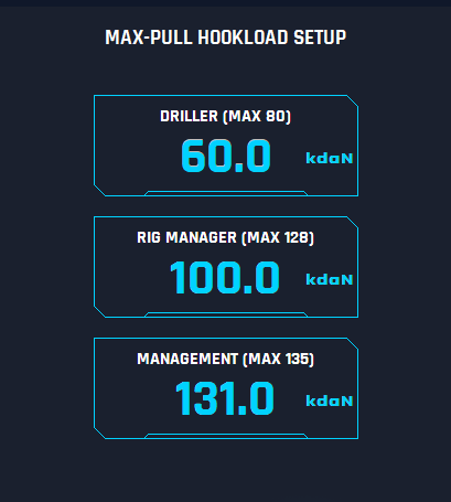
15. Max HookLoad Set up Driller: This option is to allow the driller to set how much HookLoad can be applied between 0 and 80 dAN. A window with numeric keyboard must pop up on click on this button to allow user to insert the numeric values. The value is limited to 80 or the RM setting or Management setting hierarchy. If either of these logs in and lowers the value, then it will automatically be limited to that value.
16. Max HookLoad Set Up Rig Manager: This option is to allow the Rig Manager to set how much HookLoad can be applied between 0 and 128 dAN. When pushing the button set, a window with numerical keyboard must pop up to allow the user to insert the value. Which are from 0 to a maximum of 128 or the value of management if it is lower than 128.
This option is only available for Rig Manager and Management permissions.
17. Max HookLoad Set Up Management: This option is to allow Management to set how much HookLoad can be applied between 0 and 135 dAN. When pushing the button set, a window with numerical keyboard must pop up to allow the user to insert the value. which are from 0 to a maximum of 135. If the Management user selects a value that is less than the RM and Driller, those will automatically be reduced to this value.
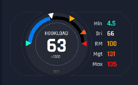
18.HookLoad: This is a display to show the current Hookload value. The triangles around the dial indicate the min, max, and profiles hookload settings.
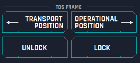
19. TDS Frame: This parameter represents the movements of the frame, which is the mount of top drive. On this panel the user can control this frame.
Transport Position: Click on this button will start the movement for the top drive to the inner part of the MAST and ready for transportation. Only moves while pressed.
Operation Position: Pushing this button the top drive will be moved outside the mast and be ready for operation. Only moves while pressed.
Lock: This button allows the user to lock the top drive once it is in Transport position
Unlock: When the Top Drive is in transport position, user can push this button to unlock the top drive and move it outside the mast by the operation position button.
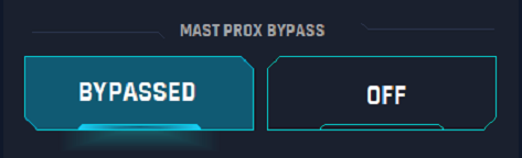
21. Mast Prox: Drawworks will not function from Driller’s Cabin if Mast Pins are not engaged. Bypass buttons disable that behavior.
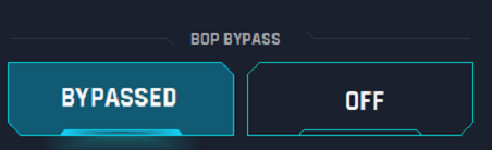
22. BOP Bypass: BOP Bypass will allow movement of drawworks with Pipe Rams Closed.
Behavior: A signal from the BOP accumulator system that is for pipe rams closed. This is to stop the drawworks upward motion, doesn’t impact downward motion. Allow upward movement limited to 5% drawworks speed and limits weight to 10 KdaN. If in a well control situation, one can set the pipe, lift, and clear the blocks from the area but prevents being able to pull the pipe into the pipe rams and causing damage.