
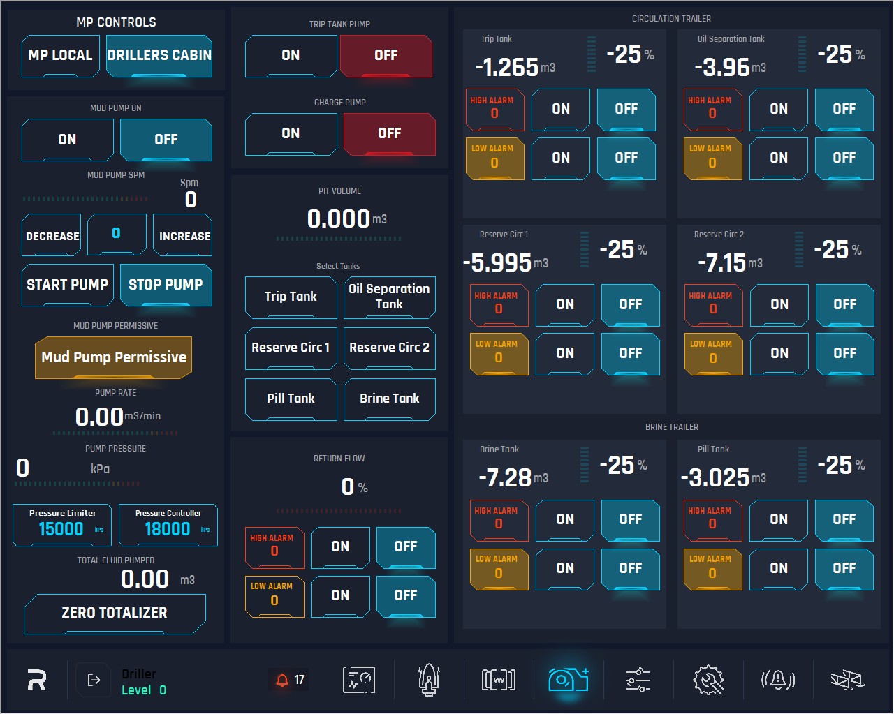
Mud Pump Page
1. Mud Pump Control buttons:
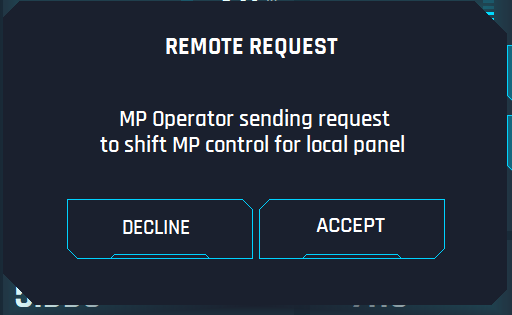
MP Local: When pushing this button, the control for mud pump should be given to Screen on mud pump skid and the complete mud pump panel, trip tank pump and charge pump must be locked on Driller Cabin, so the driller can only use Tanks, Return Flow and Pit volume panels. If Mud Pump is controlled from Driller Cabin and MP is running (SPM > 0) and Operator wants to take control from the Local panel, Operator needs to press the “Local” button and pop-up window will be open on Local Panel (see image below).
-20250821-071038.png?inst-v=58235f4f-24eb-4987-b704-1f41f18d29f9)
The following pop-up window will be open in the Driller Cabin HMI (see image below). If the Driller accepts, the MP window will close, and operator can operate MP locally by the HMI. If the Driller declines or does not do anything within 30 seconds, both pop-up windows will close, and the control will keep in Driller Cabin.
Driller Cabin: When pushing this button, the control will be given to Driller Cabin and the user is able to control all the parameters on this page.
Note: Driller Cabin is the master and Mud Pump is the slave, that means, who can give or remove the controls is the Driller cabin not the mud pump skid screen. If the Hoist HMI is not in the network, then the pump controls default to pump and allow the pump to function without the hoist online.
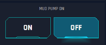
Mud Pump VFD: This handles the VFD for the MP, user can turn on or off the VFD.
ON: Switch on the VFD. When the button is pressed, it turns yellow until the system confirms all the signal/permissive are engaged, and then turns green.


OFF: Switch off the VFD.
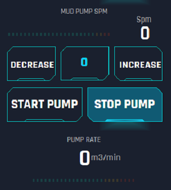
Pump Stroke Per Minute: This left display shows the current SPM.
Set (Yellow SPM) Button: When the button is pressed, user can set the value for SPM, this can be done before or after starting the pump. This is limited to 300 SPM and must be E-Tech changeable only. If the operator wants to pressure test with a slow pump speed, they can select from 1 to the set value on the set-up page (300). This will override the default of 25 SPM, if the operator sets the value for 25 and or any value above, then the default will start the pump with 25 SPM.
4. Start Pump: Starting pump and reach 25 SPM by default automatically. This 25 SPM is by default value (unless the system is set for a value less than 25), so each time the pump is started it will start at this value UNLESS the user sets a specific SPM in the MUD PUMP PAGE that is less than 25 SPM. Then, the user can decrease or increase this value by the corresponding buttons.
5. Stop Pump: Stopping the pump.
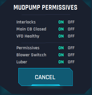
Mud Pump Permissive: Green colour of the button informs that all required permissive are healthy.

If the colour of the button is yellow, then one of the permissive conditions is not healthy.

Click on the Mud Pump Permissive button expands the dialogue with the permissive conditions list and its states.
7. Pump Rate: This is a visualization display to show the current value of the pump rate. The bar below represents the values in colour, green, yellow and red.
8. Pump Pressure: Left display to show the current value of the pump (standpipe) pressure. The bar below shows the scale from 0 to maximum E-tech value set.
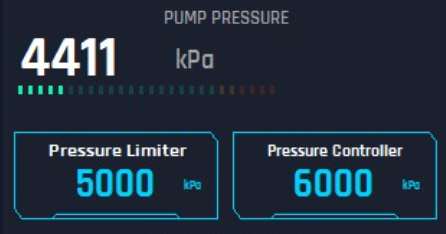
Pressure Limiter: If pump reaches this value, it will automatically decrease the set point SPM to keep working but at less SPM. Click on the field to edit the Pressure Limiter value.
Pressure Controller: The maximum pressure the pump should reach, if pump exceeds this limit, it will automatically turn off. Click on the field to edit the Pressure Controller value
9.Total Fluid Pumped: This is only a display to show the current total fluid pumped. This value will increase from the start of the pump till user decides to make 0 by the ZERO TOTALIZER button, this button will make 0 the total fluid pumped (reset) the counter.

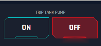
Trip Tank Pump: This is the pump on the trip tank.
ON: Start the pump - Green when activated

OFF: Stop the pump - Red when deactivated
Charge Pump: This is the charge pump
ON: Start the pump Green when activated

OFF: Stop the pump Red when deactivated

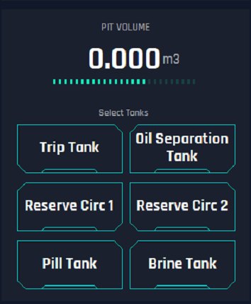
12. Pit Volume: This is a display to show the total volume of the pits that the user has selected on this section. Users can select many at the same time and all the values will be added or subtracted.
Touching the tank button once selects it, touching a second time deselects it. They can select any or all tanks for this pit volume calculator.
13. Return Flow: This display shows the return flow value in percentage.
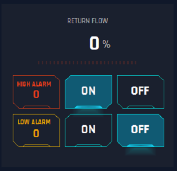
High Alarm: Alarm for high level on the tank and it triggers the horn in Drillers Cabin.
Behavior: When pressed, a keypad scale should appear, and value can be selected from 1 to 100%.
ON: Activate the set up for high Alarm
Behavior: When pressed it starts the alarm and should be highlighted as active
OFF: Deactivate the set up for high Alarm
Behavior: When pressed it stops the alarm and should be highlighted as active. When this is touched it should pop up and acknowledge that selecting this is turning of the alarm permanently.
Low Alarm: Alarm for low level on the tank and it triggers the horn in Drillers Cabin.
Behavior: When pressed a keypad scale should appear, and value can be selected from 1 to 100% but it is limited by the HIGH ALARM setting, this value can never be equal or greater than the HIGH ALARM setting.
ON: Activate the set up for low Alarm
Behavior: When pressed it starts the alarm and should be highlighted as active
OFF: Deactivate the set up for low Alarm
Behavior: When pressed it stops the alarm and should be highlighted as active. On clicking the pop up appears to acknowledge that selecting this is turning of the alarm permanently.
When an Alarm is activated, an alert warning will pop up on the HMI with an “Acknowledge” button to silence for 2 mins.

Alarms for Pits
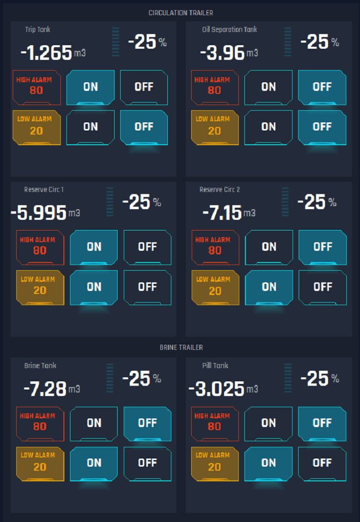
High Alarm: Alarm for high level on the tank and it triggers the horn in Drillers Cabin.
Behavior: When pressed a keypad scale should appear, and value can be selected from 1 to 100%.
ON: Activate the set up for high Alarm
Behavior: When pressed it starts the alarm and should be highlighted as active
OFF: Deactivate the set up for high Alarm
Behavior: When pressed it stops the alarm and should be highlighted as active. When this is touched it should pop up and acknowledge that selecting this is turning of the alarm permanently.
Low Alarm: Alarm for low level on the tank and it triggers the horn in Drillers Cabin.
Behavior: When touched a keypad scale should come up and they can select from 1 to 100% but it is limited by the HIGH ALARM setting, this value can never be equal or greater than the HIGH ALARM setting.
ON: Activate the set up for low Alarm
Behavior: When pressed it starts the alarm and should be highlighted as active
OFF: Deactivate the set up for low Alarm
Behavior: When pressed it stops the alarm and should be highlighted as active. On clicking the pop up appears to acknowledge that selecting this is turning of the alarm permanently.