PLC Settings
On the settings page, displayed you can change the main parameters and display settings. The page consists of several tabs with different settings. To switch to the necessary tab click on its title at the top of the page.
Hole settings
On the Hole settings tab in the PLC Settings hole parameters can be specified.
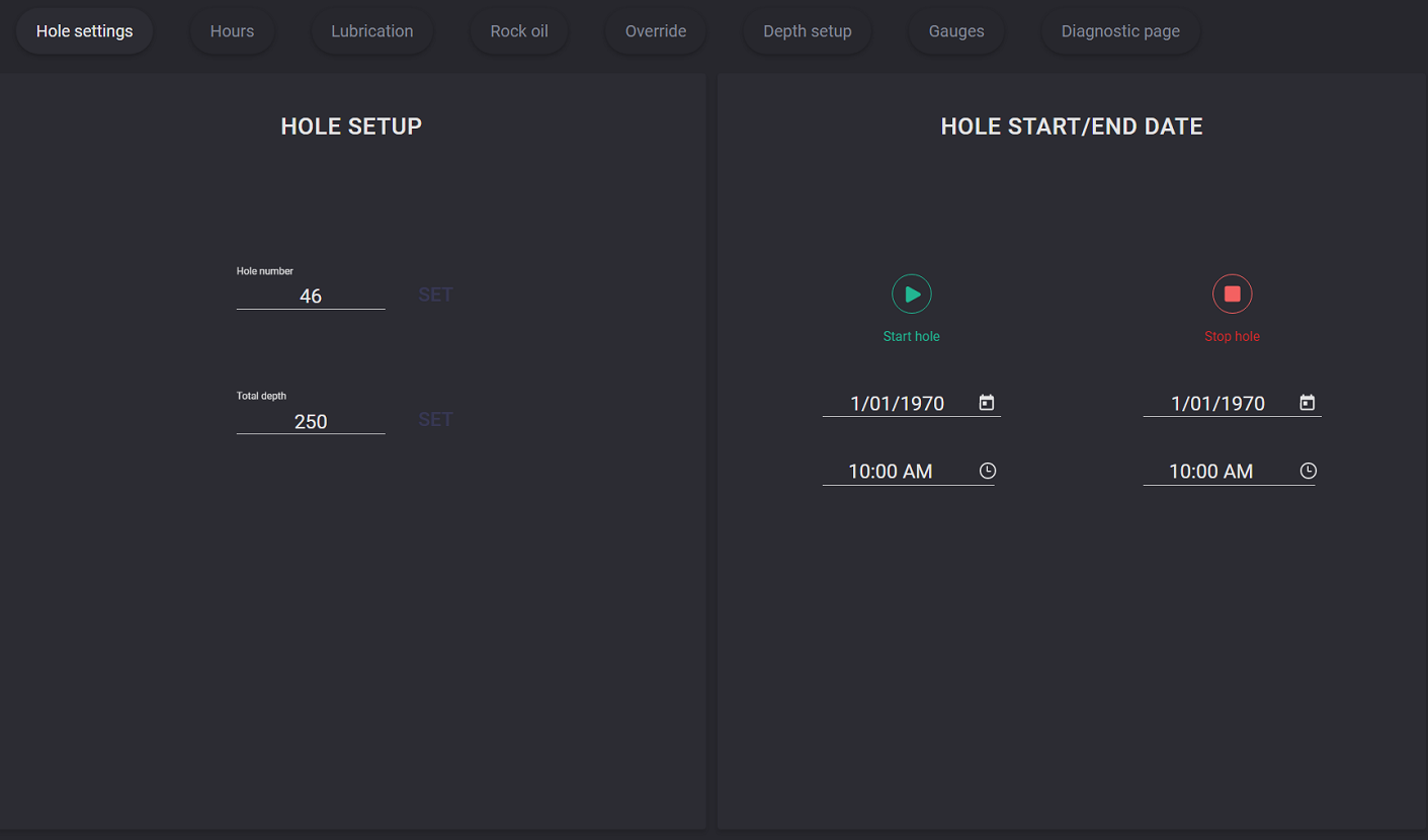
To define the hole number put the cursor to the field and enter the number on the expanded keypad. Click on the Set button to apply entered number.
To specify target depth put the cursor to the field and enter the value on the expanded keypad. Click on the Set button to apply the entered value.
The hole can be started or stopped on the hole settings tab by clicking the corresponding button. If the hole is already running the Start button will be locked. The start and end date and time can be changed. Click on the calendar icon in the date field expands the date picker and the selected date will be placed into the field. Click on the clock icon in the time field expands dial-piece and selected start/end time will be set up.
Hours
On the Hours tab index dials for Engine, Compressor, Drill, and Propel hours are displayed. Total hours value displayed in the field on the index dial.
Engine and Compressor hours can be reset by clicking on the reset button.

Note: to reset value password should be entered
Lubrication
Lubrication parameters are displayed on the corresponding tab. Toggle the button to the On position to start the lubrication. To turn on lubrication the password should be entered. The lubrication start timer can be set to postpone the start process. Enter minutes when the timer goes off and click on the Set button.
When the lubrication is on the pulse value will be displayed in the corresponding field.
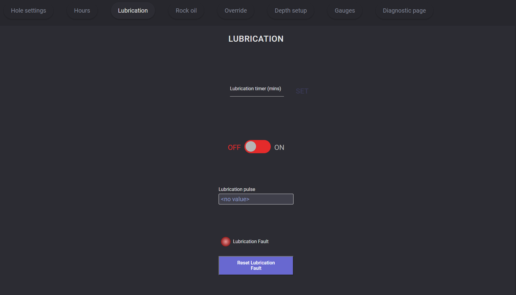
The status of the process is displayed by the light indicator “Lubrication Fault“.
Rock oil
The rock oil process can be turned on on the corresponding tab of the settings. Toggle the button to the On position to start the process. To turn on the rock oil process the password should be entered.
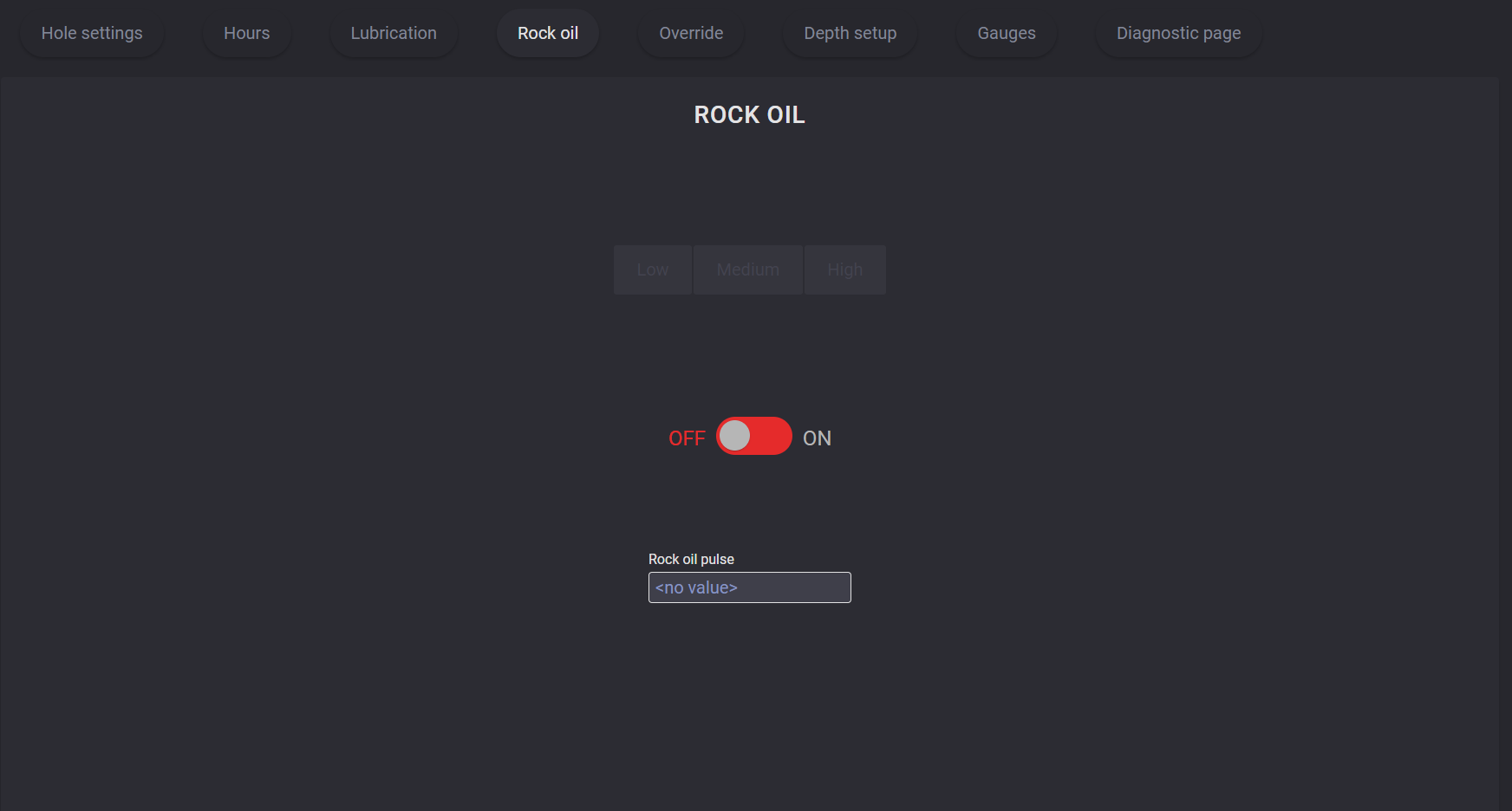
When the rock oil is on the pulse value will be displayed in the corresponding field.
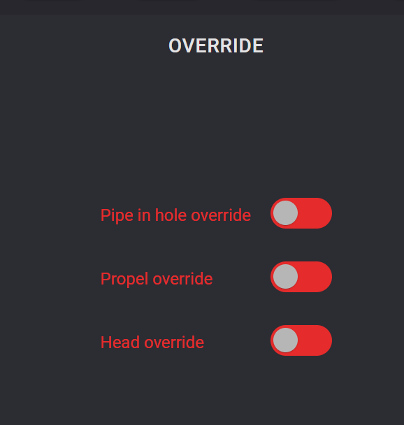
Override
Blocking of the automatic control can be performed on the Override tab of the Settings. To turn on or turn off the Pipe in hole override, Propel override and Head override toggle the corresponding button into ON/OFF position. To perform it you need to enter the password to confirm the action.
Depth setup
Depth parameters, laser calibration, setpoints can be configured on the Depth setup tab.
To specify a top or bottom parameter to calibrate the laser enter the value to the Top (mm) and Bottom (mm) fields and click on the Set button to apply changes. The set value will be displayed in the Setpoint field.
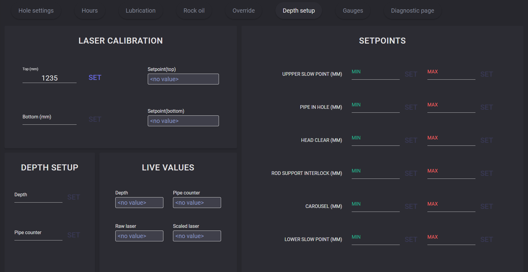
To define the ranges for the Upper slow point, Pipe in hole, Head clear, Rod support interlock, Carousel, Lower slow point parameters enter minimum and maximum setpoints values and click on the Set button. To apply setpoint for any parameter you will be asked for a confirmation password. In the Depth setup block can be entered Depth and pipe counter values.
Current Depth, Pipe counter, Raw laser, and Scaled laser values are displayed in the Live values block.
Gauges
On the Gauges presented dial scales for different parameters:
pulldown pressure;
rotation pressure;
CS track pressure;
NCS track pressure;
auxiliary pressure;
bit air pressure;
holdback pressure;
compressor oil pressure;
engine oil pressure;
compressor discharge temp;
hydraulic oil temp;
water level;
fuel level;
coolant temperature.
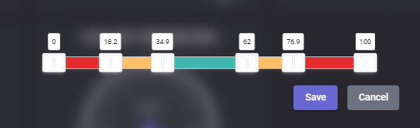
Warning and alarm ranges can be defined for the parameters marked with the gear icons. Click on these icons opens the modal window with scale to define the ranges. The warning and alert range can be changed by dragging the sliders to the necessary values. When the ranges are selected, click on the Save button to apply values on the dial scale.
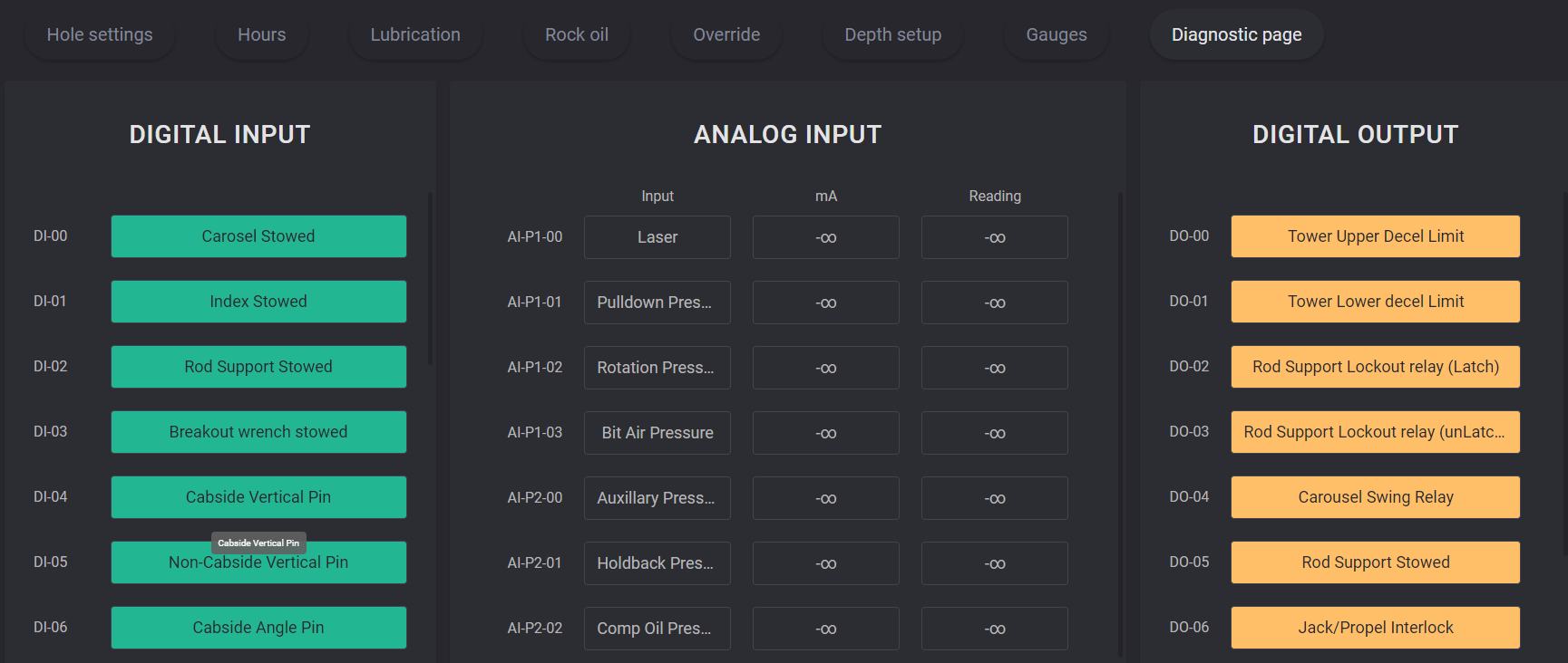
Diagnostic page
On the diagnostic page, pin definition for signals on Digital input displayed in the left block and pin definition for Digital output presented in the right part. If the pin is not assigned, its field will be empty.
For Analog input, displayed pin definition and values of the current signals in the mA column and reading signal in the Reading column.