
Monitoring Page
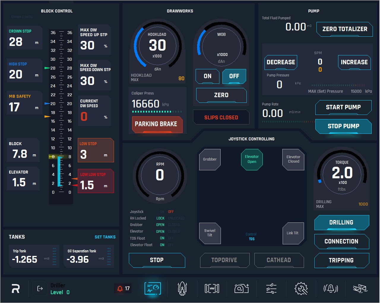
The Monitoring Page provides a real-time view of the main drilling parameters, allowing the user to closely monitor the operation's progress. This page displays critical data such as pressure, torque, hookload, and other essential metrics, ensuring the user stays well-informed. In addition to viewing these parameters, the user has access to several basic functionalities to interact with the system as needed. This page is designed to offer an intuitive and efficient overview of the drilling process.
Features and indicators description:
Centre Scale: Represents the full height and scale of the mast. It also includes a function where, when the block height reaches the MB (Monkey Board) point and passes it, the section from 22m to 36m (Ground Level) is highlighted in yellow. These values are set on the Drawworks page.
There is a mark on the mast (also represented on the scale by a yellow triangle at 8m) at a fixed height, where the operator should stop the elevator and perform the calibration.
Ground Level: Left Scale Represents the Ground Level to the top of the mast.
Rig Floor Level: Right Scale Represents Rig Floor Level to the top of the mast.

Block indicator: Indicates the distance from the rig floor to the top of the block.
Block = (bottom of) ELEVATOR position + 6.40m. This is a hardcoded value; user cannot edit it.

Elevator: Indicates the distance from the rig floor to the bottom of the elevator.
Max (set) DW Speed: Indicates the max speed the drawworks currently set at (value is presented in %), only visualization. This value can be set in Ops Parameter Page based on hierarchies.
Current DW Speed: This is an indicator to show the current DW velocity, in percentage %. Only for visualization purposes.
Crown O Matic Alarm: This Alarm will be activated when the Crown Saver device is activated. This is a mechanical device installed on drawworks.

Crown Stop: This is a visualization display to show the set point for Crown STOP (Ground Level). This value is set on the Drawworks page.
High Stop: This is a visualization display to show the set point for High STOP (Ground Level). This value is set on the Drawworks page.
Monkey Board Stop: This is a visualization display to show the set point for Monkey Board STOP. (Ground Level) This value is set on the Drawworks page.
10. Low Stop: This is a visualization display to show the set point for Low STOP (Rig Floor Level). This value is automatically hardcoded 1m above Low Low Stop.
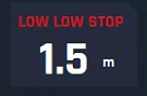
11. Low Low Stop: This is a visualization display to show the set point for Low STOP. (Rig Floor Level) This value is set on the Drawworks page.
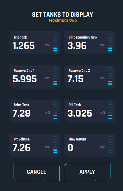
12. Tanks: This is a panel that shows a quick view of the selected tanks.

13. Set Tanks: This button allows the user to select the tanks the Driller wants to monitor during operations.
14. HookLoad: This is a display to show the current Hookload in daN. The round bar scale indicates the value that must be scaled to the MAX set hookload value.
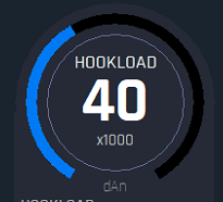
15. Max (set) Hookload: This is an indicator where user can see the max value set as per the profile logged.

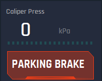
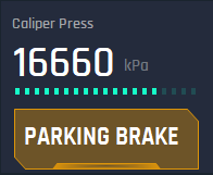
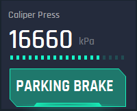
16. Caliper Press: This is a display to show the current Pressure of the Caliper in kPa, when there is no pressure it means, caliper is locked to Drawworks. When it gets a certain pressure, the caliper gets unlocked. The Parking Brake button by default must be red which means brakes are parked and no pressure. When user press Parking Brake button (or toggles the DW joystick), HMI will send a trigger command to the CPU to do a torque check, load the motor/brake resistor accordingly and release the calipers, then it will get unlocked from the Drawworks. During this process from the time the park button is pressed to release or the DW joystick is toggled, the button becomes yellow first until the CPU determine all the values, permissions and confirmations are done, at which point it will change to green to indicate brakes are released.
Brakes Applied
Command Sent to Release Brakes
Brakes Released
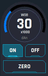
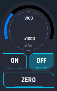
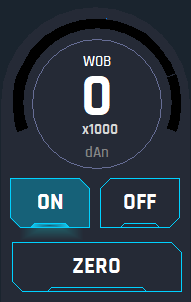
17. Weight on Bit (WOB): This is a display to show the current WOB in daN unit. It has 3 buttons:
ON: Clicking on this button will display the value of the WOB on the dial during drilling operations;
OFF: Clicking on this button will hide the WOB value since when the rig is not drilling this value is useless as it is showing wrong value;
ZERO: Clicking on this button will make the current WOB value set to 0 daN.
On
Off
Zero
18. SLIPS: This display shows slips status, when OPEN or CLOSED.


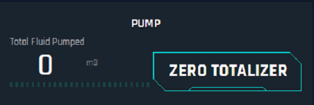
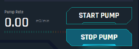
19. Total Fluid Pumped: This display shows the current total fluid pumped in m³. This value will increase from the start of the pump till the user decides to set it to 0 by pressing the ZERO TOTALIZER button, this button will set the total fluid pumped (reset) to 0 the counter.
20. Strokes Per Minute SPM: The white numbers indicate the current SPM at which the pump is running. The yellow numbers indicate the MAX SPM that the mud pump can reach on the current operation. This value must be set on the mud pump page. The system will not exceed the MAX SPM value.
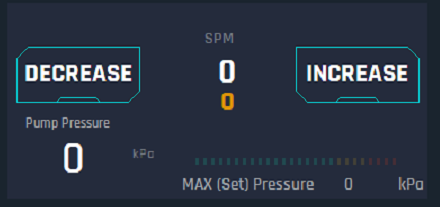
21. Decrease: After starting the Pump the user can decrease the speed of the pump by 5 SPM per push till desired SPM is reached.

22. Increase: After starting the Pump the user can increase the speed of the pump by 5 SPM per push till SPM is reached. If the user holds it for 3 seconds, it should reach the maximum selected speed.

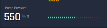
23. Pump Pressure: This display shows the current pump pressure in kPa. The bar lights next to it work as follows: Green: From 0% to 70% of the scale. Yellow: From 70% to 85% of the Scale. Red: From 85% to 100% of the Scale, this scale would be based on the selected or set maximum pressure.
Max set Pressure: This is an indicator to show the Maximum pressure set for operations.
24. Start Pump: Click on this button will send a command to CPU for starting pump and reach 25 SPM by default automatically. This 25 SPM should be set as default value, so each time the pump is started it will hold at this speed, until the operator increases it by touching and releasing or holding for 3 secs the Increase button. Then, the user can decrease or increase it by the corresponding buttons.
25. Stop Pump: Click on this button will send a command to CPU to stop the pump.
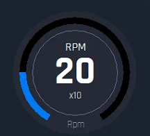
26. RPM Dial: This display shows the current RPM of the TOP DRIVE. The blue circle bar on the dial will adjust its movement based on the RPM settings. For instance, when Drilling, the max scale of the blue circle bar must be the MAX RPM DRILLING.
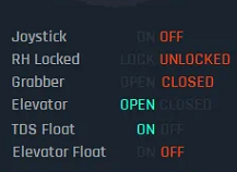
27. Joystick indicator: Shows the status of the device, ON state means the joystick is active and is being used, OFF state means the Joystick is not being used because manual mode is activated. If both options are grey, it means there is a malfunctioning of the joystick.
28. RH Locked: This is an indicator of the Handling Ring Pin state, LOCKED means the sensor sent the signal to indicate HR is locked and UNLOCKED means the HR is not LOCKED. A Proxy Sensor handles this state.
29. Grabber: This is an indicator of the grabber state. There are OPEN and CLOSED states. If both are grey it means malfunctioning of the grabber.
30. Elevator: This is an indicator of the elevator's state. There are OPEN and CLOSED states. If both are grey it means malfunctioning of the elevator.
31. TDS Float: This is an indicator of the TDS Float mode state. There are ON and OFF states. If both are grey that means its malfunction.
32. Elevator Float: This is an indicator of the Elevator Float mode state. There are ON and OFF states. If both are grey that means its malfunction.
33. Stop: Click on this button will send a command to CPU to stop the rotation of the TDS.

35. Top Drive: Click on this button allow to select the control mode of the joystick (the Joystick is by default on this mode), so, if user select top drive the joystick will take control of the top drive and 3 more buttons at the right will appear: DRILLING, TRIPPING, MAKE UP, BREAK OUT.
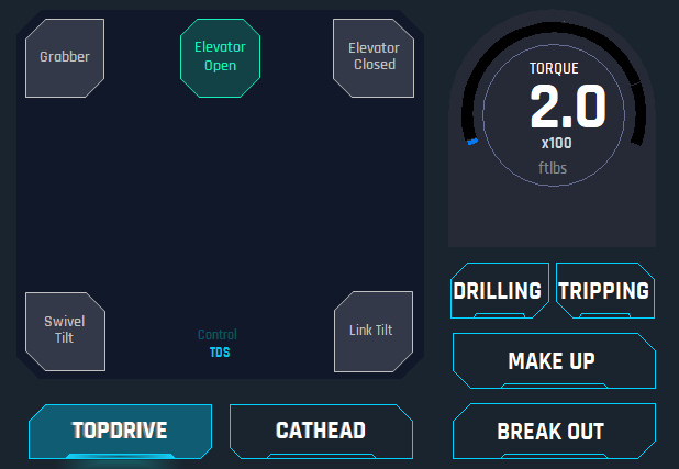
Drilling
When Drilling mode is selected and rotation is greater than 0, the right thumb wheel to control RPM is displayed on the joystick controlling panel and all the buttons on the joystick are deactivated. Note that this Joystick controlling panel is directly related with the buttons on the joystick. Additionally, in drilling mode, the system must use the RPM and TORQUE max settings on maintenance page to apply to TOP DRIVE limiting set parameters.
Important: Drilling controls are defined. TDS must be stopped to change joystick selection.
All grabber last command must be confirmed as open and then all functions are locked out
Swivel Tilt must be confirmed as float, all functions are locked out.
Link Tilt is fully functional.
Elevator is fully functional.
When bumping the right thumb wheel upwards the first time it will start rotation, then individual bumping the thumb upwards user will increase the RPM by 5 RPM till get the desired RPM. Note, that once the thumb wheel is back in the center it will not stop the rotation.
When bumping the right thumb wheel downwards user can decrease the RPM by 5 RPM till get the desired RPM.
If push and hold for 3 seconds the right thumb wheel upwards, it will go straight forward to MAX RPM Set Point.
When the rotation stops, it has the option to move from drilling to connection or trip modes.
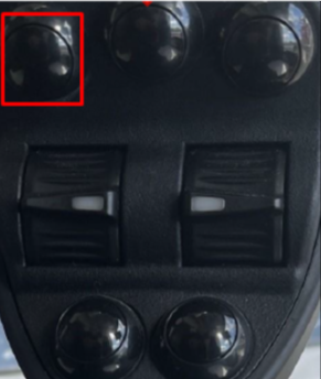
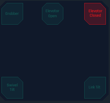
Grabber
To use the Joystick grabber, user has to press the left-up corner button (on the joystick) as shown on the joystick controlling panel, then it will have only 4 movement: UP (moving joystick forward), DOWN (moving joystick backward), OPEN (moving joystick to the left) and CLOSE (moving Joystick to the right). Button will be highlighted when activated.

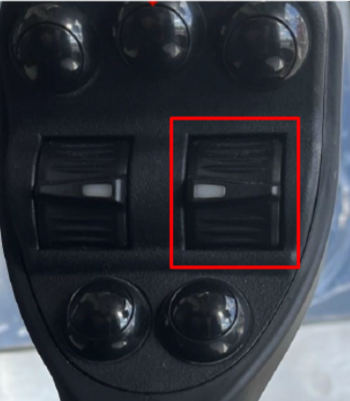
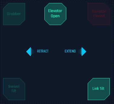
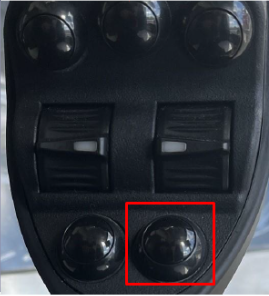
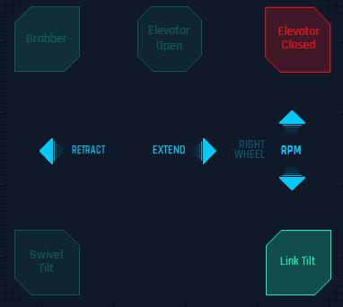
Swivel Tilt
To use the Swivel Tilt by the Joystick, user has to press the bottom left button (on the joystick) as shown on the joystick controlling panel, then it will have 2 movements: RETRACT (move the joystick to the left) and EXTEND (move the joystick to the right). Button will be highlighted when activated.
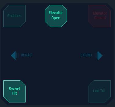
Link Tilt
To use the Link Tilt by the Joystick, user has to press the bottom right button (on the joystick) as shown on the joystick controlling panel, then it will have 2 movements: RETRACT (move the joystick to the left) and EXTEND (move the joystick to the right). Button will be highlighted when activated.
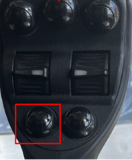
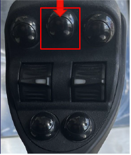
Elevator Open
To open the elevators, user has to press the center up button (on the joystick) as shown on the joystick controlling panel. Button will be highlighted when activated.
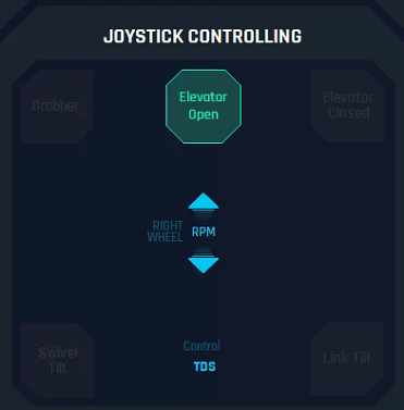
Interlock: It is not possible to open elevators if the weight is greater than 6,000 daN (6k). E-Tech Profile should be able to change it on Ops Parameter Page
Elevator Close
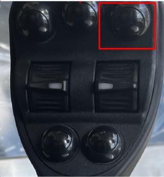
To close the elevators, user has to touch the right up corner button (on the joystick) as per the joystick controlling panel shows. Button will be highlighted when activated.
Connection Mode (Make Up – Break Out)
On pressing any of the buttons, the software sets the control mode to joystick for connection mode. During Connection mode user can control the RPM which is set to 20 RPM by default. To activate make up operations press the makeup button; to break out press break out button.
Connection Mode: Controls defined. TDS must be stopped to change joystick selection
Grabber is fully functional if TDS is stopped (Interlock - Grabber Open/Close Functions locked when TDS is Rotating).
Swivel Tilt is fully functional if TDS is stopped. (Locked when TDS is rotating)
Link Tilt is fully functional.
Elevator is fully functional.
RPM control is limited to 0 to 20 RPM, both directions.
Torque selected parameters for connection are active in right (make up direction).
When user presses and holds the right thumb wheel upwards full up, rotation will start and go straight forward to 20 RPM, center position is ZERO and between those 2 points the speed is variable. If pushing upwards the top drive is making up and the interlock “Max Torque while connection” will be working. If thumb wheel comes to the center, rotation stops.
When user presses and holds the right thumb wheel downwards, rotation will start and go straight reverse to 20 RPM - If pushing downwards the top drive is breaking out to 20 RPM and there is no limitation on TORQUE. If thumb wheel comes to the center, rotation stops.
When connection user can control Grabber, Swivel Tilt, Elevators, Link Tilt and RPM.
Grabber, Swivel Tilt, Elevators, and Link Tilt work exactly similar in all the modes for TOP DRIVE.
Tripping Mode
By pressing the Button, the right thumb wheel on the joystick will be deactivated since there is no need to control RPM on this mode and user can control Grabbers, Elevators, Swivel Tilt and Link Tilt as mentioned before, here the behavior is the same. In addition, Swivel Tilt will be set in FLOAT mode automatically when this mode is activated.
Tripping Mode:
All grabber last command must be confirmed as open and then all functions are locked out
Swivel Tilt all functions are locked out.
Link Tilt is fully functional.
Elevator is fully functional.
TDS rotation is locked out.
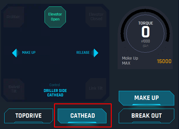
36. Catheads:
When user presses the button on the HMI, two options will appear on the right side: Make Up and Break Out.
Make Up: When pressing this button on the HMI, the joystick will control the Driller Cabin side (DS) Cathead and it will allow only 2 movements with the joystick: LEFT (Release) and RIGHT (Make Up), these movement will also be displayed on the joystick controlling panel as informative. When this button is pushed the system will set the control for catheads to Joystick and “Cat Head Make Up Max Torque” interlock will be working. The speed of the movements is governed by joystick movement, torque is limited as per setting. If controlled by the buttons, then they are one speed only.
Break Out: When pressing this button on the HMI, the joystick will control the Off Driller Cabin side (ODS) Cathead and it will allow only 2 movements with the joystick: LEFT (Release) RIGHT (Break Out), these movement will also be displayed on the joystick controlling panel as informative. The speed of the movements is governed by joystick movement, torque is NOT limited to break out. If controlled by the buttons, then they are one speed only.
When Catheads is being controlled by the joystick, all the buttons on the joystick will be deactivated.
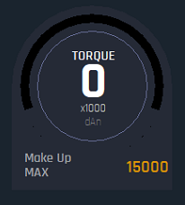
37. Torque Dial: This is display that shows the torque of the current system activated, either TOP DRIVE or CATHEADS.
38. Max Torque Drilling Display: This is a display that shows the Max Torque Drilling set, this should be displayed when TOP DRIVE > DRILLING is activated.

39. Max Torque Connection Display: This display shows the Max Torque Drilling set, this should be displayed when TOP DRIVE > CONNECTION is activated

40. Make Up Max Torque: This display shows the Max Torque for make up when CATHEADS > MAKE UP is activated.